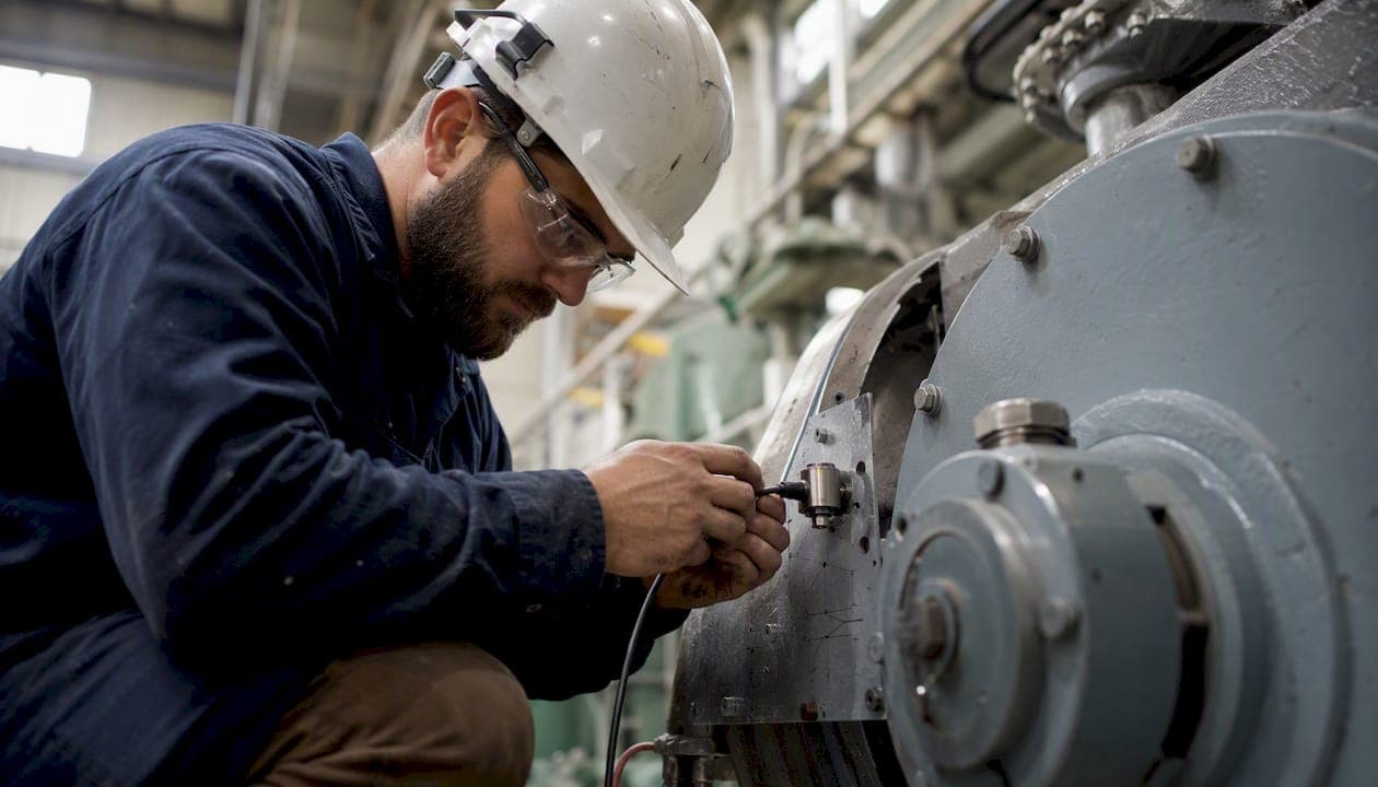
For most functioning legacy machines that aren't generating usable data, retrofitting sensors is the right first move. Buying new equipment to get IIoT capability rarely pencils out when the machine itself still runs well. The smarter path is to add non-invasive sensors, connect them through a local gateway, and start collecting the signals that predictive maintenance models actually need. Here's how to start:
- Assess criticality (Day 1–30): Rank your machines by failure impact and maintenance cost. Pick 6–12 that represent your worst failure modes and have accessible mounting points for vibration, current, or temperature sensors.
- Run a focused pilot (Day 30–90): Deploy sensors on your shortlist, define two or three specific failure modes you're targeting, and set measurable success criteria before you start collecting data.
- Evaluate and scale (Day 90–180): Review pilot metrics against your targets. If the signal quality is clean and the alerts are actionable, expand to the next tier of machines.
A pilot covering 6–12 machines typically runs $15,000–$50,000 all-in (sensors, gateway hardware, engineering time, and analytics setup), depending on sensor count and integration complexity. That's a fraction of what a single equipment replacement costs.
Key Takeaways
Retrofitting sensors on legacy manufacturing equipment is the right first step for most facilities: it costs a fraction of replacement, can be done without halting production, and delivers measurable predictive maintenance results within 6–18 months.
| Point | Details |
|---|---|
| Start with a focused pilot | Select 6–12 machines covering your worst failure modes; define success criteria before deploying hardware. |
| Retrofit costs 5–15% of new equipment | Non-invasive sensors and a gateway typically cost far less than replacement, with pilots running $15,000–$50,000 all-in. |
| Mounting consistency drives model accuracy | Photograph every sensor installation and log mounting metadata; inconsistent placement invalidates training data. |
| Edge processing is required at scale | Compute FFT and RMS locally on the gateway to avoid saturating shop-floor networks with raw waveforms. |
| Gembalabs connects sensor data to production context | The platform maps equipment signals to batch IDs, shift records, and operator notes for food-plant compliance and predictive maintenance. |
Table of Contents
- Why retrofit sensors in manufacturing, and when does replacement make more sense?
- Which retrofit sensors to install first and where to mount them
- What a practical retrofit IIoT architecture looks like
- Non-invasive installation methods that protect your warranties
- Step-by-step retrofit plan: from assessment to plant-wide scale
- What the data pipeline needs to deliver for predictive maintenance
- Common retrofit pitfalls and how to avoid them
- Pilot evidence and measured outcomes from retrofit projects
- Applying retrofit sensors in food manufacturing: compliance, MES integration, and operational fit
- What retrofit pilots actually teach you (and what most guides skip)
- Gembalabs makes the pilot faster for food manufacturers
- Sources
Why retrofit sensors in manufacturing, and when does replacement make more sense?
Retrofitting, in an Industry 4.0 context, means adding sensors and IoT components to existing machines so they can participate in digital workflows without being replaced. The machine keeps running. You add intelligence around it.
The business case usually falls into four categories: predictive maintenance (catching failures before they happen), OEE improvement (measuring actual uptime, cycle time, and quality rate), energy monitoring (tracking motor load and identifying waste), and traceability (recording process conditions against batch IDs for compliance).
When does retrofit make sense? Use these criteria:
- The machine has at least 5–7 years of remaining useful life
- Replacement cost exceeds $50,000 and the machine runs reliably
- The machine has accessible bearing housings, motor terminals, or surface areas for sensor mounting
- Failure modes are known (bearing wear, overheating, motor degradation) and worth predicting
- The machine lacks any existing data output (no PLC historian, no OPC-UA server)
When to replace instead: If the machine is already failing frequently, has no accessible mounting points, or sits inside a warranty that prohibits any physical modification, replacement or a full OEM upgrade is the cleaner path.
Retrofit cost commonly falls in the 5–15% range of the price of equivalent new equipment, according to IoT retrofit guidance from KERN-IT, and the work can typically be done without halting production. For an SME running a food line, that math is hard to ignore.
Published pilot data reinforces the ROI case. A precision manufacturer connected 140+ CNC machines using clip-on sensors and BLE mesh, achieving a €720 per-machine retrofit cost and roughly 40% reduction in unplanned downtime within 18 months. That's the kind of payback that justifies a pilot before anyone asks for a capital budget.
Which retrofit sensors to install first and where to mount them
Not all sensor types deliver equal value on day one. Prioritize based on the failure modes you're targeting, not on what's easiest to install.
Priority sensor types, in order:
- Accelerometer (vibration) sensors: The highest-value sensor for rotating equipment. Mount on bearing housings, as close to the bearing race as possible, in a consistent orientation (typically triaxial: X, Y, Z). These feed FFT analysis for bearing defect frequencies, imbalance, and misalignment. MEMS accelerometers with sampling rates of 1–25.6 kHz cover most industrial applications.
- Clamp-on current sensors (split-core CT / Rogowski coil): Clip onto motor power leads without breaking the circuit. They reveal motor load, starting current anomalies, and electrical imbalance. A Rogowski coil handles high-current or oddly shaped conductors where a split-core CT won't fit cleanly.
- Temperature sensors (thermocouple, RTD, IR): Surface-mount thermocouples and RTDs track bearing and motor housing temperature trends. Infrared (IR) sensors are non-contact and useful for rotating parts or areas where adhesive won't hold. Use IR for spot checks and surface-mount probes for continuous trending.
- Acoustic sensors (structure-borne ultrasound): Detect early-stage bearing defects and air/steam leaks at frequencies above what accelerometers typically capture. Useful as a secondary layer on high-value assets.
- RPM / shaft-count sensors: Magnetic or optical sensors on rotating shafts give cycle counts and speed data. These are the simplest signals to collect and often the most useful for cycle-based maintenance scheduling.
- Simple cycle counters: A proximity sensor or photoelectric sensor counting part passes or machine cycles. Low cost, high value for scheduling preventive maintenance by actual cycles rather than calendar time.
Placement rules that matter:
Mount vibration sensors on the bearing housing, not on the machine frame. Every inch of distance from the bearing adds structural damping that attenuates the defect frequencies you're trying to detect. Use a consistent orientation across all machines of the same type — if you mount the X-axis radially on one machine, do it on all of them. Inconsistent orientation makes cross-machine model training unreliable.
For current clamps, place them on individual motor leads, not on a shared bus. You want per-motor signatures, not aggregate current.
IR temperature probes need a clear line of sight and a consistent standoff distance. Mark the target spot with a paint pen so operators re-measure from the same point every time.
Selection checklist:
- Environmental rating: IP67 minimum for most shop floors; IP69K for washdown areas in food plants
- Mounting method: magnetic mounts for quick deployment and repositioning; adhesive pads for permanent low-vibration installations; bolted adapters for high-vibration or high-temperature locations
- Sampling rate: vibration FFT needs at least 2x the highest frequency of interest (Nyquist); for bearing defect analysis, 5–25 kHz is typical. Simple RMS monitoring can run at 100–1,000 Hz.
- Power and communications: battery-powered wireless nodes work for low-duty-cycle sensors; wired or PoE for high-sample-rate vibration nodes
Where standard accelerometer housings won't fit, flexible printed sensors from manufacturers like FLEXOO can access tight geometries and conform to curved surfaces.
Pro Tip: Mounting consistency is the single biggest driver of model accuracy. A sensor moved 2 cm between maintenance visits can shift FFT band energy enough to generate false positives. Use a mounting template, photograph every installation, and record the exact mounting torque in your sensor metadata.
What a practical retrofit IIoT architecture looks like
The architecture doesn't need to be complex. A reliable retrofit stack has four layers: sensors, a local edge gateway, a broker or time-series store, and an analytics or dashboard layer. Keep it simple until the pilot proves the signal quality.
| Layer | Function | Common options |
|---|---|---|
| Sensors | Collect raw physical signals | MEMS accelerometers, split-core CTs, RTDs, IR probes |
| Edge gateway | Local filtering, feature extraction, buffering | Industrial PC, Raspberry Pi CM4, dedicated IIoT gateway |
| Transport / broker | Secure data relay to cloud or on-prem store | MQTT broker (Mosquitto, EMQX), OPC-UA server |
| Analytics / dashboard | Model training, alerting, CMMS integration | Time-series DB (InfluxDB, TimescaleDB), ML platform |
Protocol guidance:
MQTT is the right default for most retrofit projects. It's lightweight, pub/sub, and designed for unreliable networks. Use it for sensor-to-gateway and gateway-to-cloud transport. It handles intermittent connectivity gracefully, which matters in metal-rich shops where RF drops are common.
OPC-UA becomes relevant when you need to pull data from existing PLCs or SCADA systems alongside your new sensors. It's the industrial interoperability standard, and most modern PLCs support it. If your machines already have a PLC with an OPC-UA server, read from it directly rather than adding redundant sensors for signals it already tracks.
HTTP/REST is fine for low-frequency data (temperature trends, cycle counts) where latency isn't critical. Avoid it for high-sample-rate vibration data.
BLE mesh works well in smaller facilities (under 10,000 sq ft) with good node density. Wi-Fi (802.11ac/ax) handles higher bandwidth for vibration nodes. LoRaWAN suits large outdoor or multi-building sites where Wi-Fi coverage is impractical but data rates are low.
Gateway hardware priorities:
The gateway should do local feature extraction (FFT, RMS, kurtosis) before transmitting. Sending raw 25 kHz waveforms over Wi-Fi from 50 machines simultaneously will saturate most shop-floor networks. Edge processing reduces bandwidth by transmitting feature vectors rather than raw waveforms, a pattern validated in published IIoT research.
Critically: route sensor data through the gateway's own network interface, not through the machine's PLC or control network. Touching the control network risks voiding warranties and introducing latency into safety-critical loops.
Basic security checklist:
- Assign each gateway a unique device identity (X.509 certificate or pre-shared key)
- Use TLS 1.2+ for all cloud transport
- Segment sensor traffic on a dedicated VLAN, isolated from the OT control network
- Enable OTA firmware updates with signature verification
- Rotate credentials on a defined schedule and log all access
Non-invasive installation methods that protect your warranties
The goal is to collect data without touching anything the OEM controls. That means no modifications to control wiring, no drilling into machine frames, and no changes to PLC logic.
Mounting methods by situation:
Magnetic mounts are the fastest option for ferrous surfaces. They're repositionable, require no adhesive cure time, and hold reliably up to moderate vibration levels. Use them for initial pilot deployments where you may need to reposition sensors after reviewing early FFT data.

Adhesive pads (epoxy or structural adhesive) give better high-frequency transmission than magnets and are appropriate for permanent installations. They require surface prep and cure time, so plan for a maintenance window.
Bolted adapters are the most reliable option for high-vibration or high-temperature locations. A small stud-welded or tapped adapter pad on the bearing housing gives a repeatable, rigid mount. This is the only method that requires any machine modification, so confirm it's permissible before proceeding.
Clamp-on CTs require no electrical modification. Open the clamp, place it around the motor lead, close it. The validated retrofit architecture from ScienceDirect research on drilling machines used exactly this approach: external sensors collecting speed and process data without touching control wiring.
Electrical and mechanical best practices:
Run sensor cables in separate conduit from power runs. Proximity to 480V motor cables induces noise that shows up as false frequency peaks in FFT data. Use shielded cable for analog sensors and ground the shield at one end only. Add strain relief at every connector to prevent vibration from working connections loose over weeks of operation.
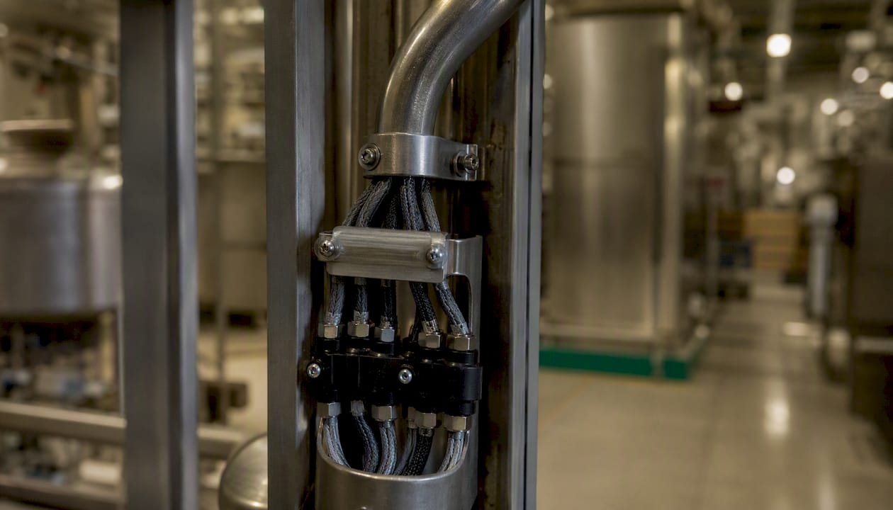
Keep sensors away from coolant spray zones unless they're rated for it. In food plants, assume everything will be hosed down and spec IP69K for any sensor in a washdown area.
Post-install signal quality checks:
Before you declare a sensor commissioned, capture a 30-second baseline waveform and run a quick FFT. You should see clean peaks at shaft frequency and its harmonics, with noise floor well below the signal. If the noise floor is within 10 dB of your signal peaks, the mounting is poor or the cable is picking up interference. Fix it before you start collecting training data.
Pro Tip: Take a photo of every installed sensor with a ruler in frame for scale, and log the mounting method, torque, and exact position in your sensor registry. Six months later, when a technician replaces a sensor after a machine repair, that photo is the only thing that guarantees consistent reinstallation.
Step-by-step retrofit plan: from assessment to plant-wide scale
Pre-retrofit machine assessment
Before ordering hardware, walk the floor with this checklist for each candidate machine:
- Age and MTBF history: machines with documented failure patterns are better pilot candidates than those with no maintenance history
- Failure modes: identify the top two or three failure modes per machine (bearing wear, overheating, belt slip) — these drive sensor selection
- Available mounting points: confirm accessible bearing housings, motor leads, and surface areas
- Electrical access: verify you can reach motor leads for current clamp installation without opening control panels
- Existing automation level: note whether the machine has a PLC, and whether it has an OPC-UA or Modbus interface you can read from
Pilot design
Select 6–12 machines that cover a diversity of failure modes and machine types. A pilot with only identical machines teaches you one failure pattern. You want enough variety to stress-test your architecture and analytics.
Pilot duration: 3–6 months is the practical minimum for vibration-based predictive maintenance. Bearing defect progression from early detection to failure typically takes weeks to months, and you need to observe at least a few complete degradation cycles to validate your alert thresholds.
Timeline
| Phase | Duration | Key activities |
|---|---|---|
| Discovery and scoping | 2–4 weeks | Machine assessment, failure mode mapping, sensor selection |
| Hardware prototyping | 2–3 weeks | Gateway setup, sensor mounting on 1–2 machines, signal validation |
| Pilot deployment | 4–6 weeks | Full sensor installation on pilot fleet, baseline data collection |
| Model training | 6–12 weeks | Feature extraction, threshold setting, alert rule configuration |
| Evaluation and rollout decision | 2–4 weeks | Pilot metrics review, cost-benefit analysis, scale planning |
Cost drivers
Sensor hardware runs $50–$500 per node depending on type and environmental rating. A gateway capable of handling 20–30 sensors costs $300–$1,500. Engineering time for installation, configuration, and analytics setup is typically the largest cost item. Analytics software and CMMS integration add recurring costs.
KERN-IT's guidance puts retrofit cost at 5–15% of equivalent new equipment cost, which for a $200,000 machine means a $10,000–$30,000 retrofit budget is realistic. A 6-machine pilot with gateway, sensors, and 40 hours of engineering time typically lands in the $15,000–$35,000 range.
Pilot success criteria
Define these before you start, not after:
- False positive rate below 10% (alerts that don't correspond to a real fault)
- Lead time to failure detection: at least 2 weeks of advance warning for bearing faults
- Reduction in emergency work orders: target 20–30% reduction over the pilot period
- Data completeness: sensor uptime above 95%
Pro Tip: Scope the pilot to one or two specific failure modes per machine type. Plug-and-play starter kits that collect everything without a defined use case fill databases without delivering ROI. Pick a failure mode, instrument for it, and prove the signal before expanding.
What the data pipeline needs to deliver for predictive maintenance
The sensor is only the beginning. The value comes from what you do with the signal between the sensor and the maintenance technician.
Data pipeline responsibilities:
| Stage | What it does | Key requirement |
|---|---|---|
| Edge filtering | Remove noise, compute FFT/RMS/kurtosis locally | Low latency, runs on gateway hardware |
| Secure transport | Encrypt and relay feature vectors to cloud/on-prem | TLS, MQTT QoS 1 or 2 |
| Time-series storage | Store timestamped features for model training and RCA | Retention: 12 months minimum |
| Model training | Build fault classifiers from labeled historical data | Requires labeled fault events |
| Alerting and workflow | Trigger work orders when health score crosses threshold | CMMS integration, defined escalation path |
Features worth extracting:
For vibration: FFT band energy at bearing defect frequencies (BPFO, BPFI, BSF, FTF), overall RMS, kurtosis (sensitive to impulsive faults), and crest factor. For current: total harmonic distortion, starting current profile, and running load variance. For temperature: rate of change, absolute value versus ambient, and trend slope over a rolling window. Cycle counts and derived health scores (normalized 0–100) make alerts interpretable to maintenance staff who aren't signal processing engineers.
Alerting workflow:
Anomaly detection fires when a health score crosses a defined threshold. That triggers a work order in your CMMS (MaintainX, Fiix, or similar) with the sensor ID, machine, fault type, and recommended action. A technician verifies the fault and closes the work order with findings. Those findings feed back into model retraining. This closed loop is what improves alert accuracy over time.
For root cause analysis, you need at least 12 months of time-series data retained at full feature resolution. Compressed or downsampled archives lose the detail needed to reconstruct what happened before a failure.
CMMS integration notes:
Map sensor asset IDs to CMMS equipment records before deployment. Define the latency SLA for alert-to-work-order creation (15 minutes is a reasonable target for predictive alerts; real-time for safety-critical conditions). Retain raw feature data for at least 12 months for compliance and RCA; retain model training datasets for the life of the model.
Common retrofit pitfalls and how to avoid them
Most retrofit pilots that fail do so for predictable reasons. Here's what to watch for:
Technical risks:
- Poor vibration sensor mounting generates noisy FFT data that makes bearing defect frequencies indistinguishable from structural resonance. Fix: use a torque wrench on bolted mounts, and validate every installation with a baseline FFT before declaring it commissioned.
- RF coverage gaps in metal-rich shops cause BLE or Wi-Fi dropouts that look like sensor failures. Fix: run an RF survey with a spectrum analyzer before finalizing gateway placement. Metal shelving and machine frames create dead zones that move when equipment is repositioned.
- Electrical noise from VFDs and motor starters induces artifacts in current sensor signals. Fix: use shielded cable, separate sensor runs from power conduit, and add ferrite cores at sensor connectors near high-current equipment.
- Battery-powered nodes in high-sample-rate vibration applications drain faster than spec sheets suggest. Fix: calculate actual duty cycle based on your sampling schedule and add 30% margin to battery life estimates.
Integration risks:
- Alert fatigue from too many thresholds set too low. Operators stop responding. Fix: start with two or three alerts per machine type, set conservative thresholds, and tune them based on verified fault events before adding more.
- Misaligned data semantics between sensor outputs and CMMS fields. A sensor reports "bearing health: 67" but the CMMS expects a fault code. Fix: define the data mapping before deployment, not after.
Organizational risks:
- No clear owner for acting on alerts. Sensors generate work orders that nobody is staffed to execute. Fix: assign a named maintenance engineer as the pilot owner before go-live.
- Operator resistance to new monitoring. Staff worry that sensors are surveillance tools. Fix: frame the pilot as equipment health monitoring, not performance monitoring, and involve operators in sensor placement decisions.
- Insufficient training on what alerts mean and what to do. Fix: run a 2-hour training session with maintenance staff before go-live, covering the three most likely alert types and the expected response for each.
Pilot evidence and measured outcomes from retrofit projects
The most detailed published case comes from a precision manufacturer that retrofitted 140+ CNC machines with clip-on vibration sensors using BLE mesh connectivity and on-device FFT processing. The methodology: sensors were mounted non-invasively on spindle housings and bearing locations, BLE mesh nodes relayed feature vectors (not raw waveforms) to edge gateways, and cloud ML models trained on labeled fault events.
What this pilot teaches:
- Edge FFT is not optional at scale. Transmitting raw waveforms from 140 machines would have saturated the network. On-device feature extraction made the architecture viable.
- BLE mesh requires careful RF planning. Metal CNC enclosures attenuate BLE signals significantly. The team ran an RF survey and placed relay nodes to maintain coverage.
- In-house installation beat external integrators on speed. Maintenance technicians who knew the machines mounted sensors faster and more accurately than outside contractors who needed machine familiarization time.
- Clip-on sensors preserved all OEM warranties. No control wiring was touched. The retrofit was entirely external.
A simpler lab-validated example: researchers at ScienceDirect demonstrated a retrofit architecture on a drilling machine, collecting speed and bore-depth data through external sensors connected to a cloud analytics pipeline. The architecture confirmed that even simple external sensor setups can feed meaningful predictive models when the signal quality is validated before training begins.
Applying retrofit sensors in food manufacturing: compliance, MES integration, and operational fit
Food plants have requirements that general manufacturing retrofits don't. FSMA traceability rules, temperature recordkeeping, and sanitation constraints all shape how you deploy and integrate sensors.
**FSMA and traceability: **
- Sensor data tied to batch IDs creates an electronic record of process conditions during production. For FSMA Section 204 compliance, temperature and time data linked to a lot code satisfies key data element (KDE) requirements for certain food categories.
- Retain sensor records for at least 2 years (FSMA minimum) with timestamps, sensor IDs, and calibration status metadata. An audit trail that can't prove sensor calibration is nearly as bad as no record at all.
- Map sensor signals to process steps and batch IDs in your MES before go-live. A temperature reading without a batch context is compliance data that can't be used. For guidance on MES integration for food SMEs, the mapping step is where most food plants underinvest.
MES and production monitoring integration:
- Use OPC-UA to pull existing PLC signals (line speed, fill weight, seal temperature) alongside new retrofit sensor data. This gives you a unified process record without duplicating instrumentation.
- Map sensor asset IDs to MES equipment records and production order numbers. Every sensor reading should carry a machine ID, timestamp, and batch reference.
- For real-time equipment monitoring in food plants, dashboards should display both equipment health scores and production KPIs on the same screen so operators don't need to switch systems.
Operational fit:
- Food plant operators work in loud, wet, fast-paced environments. Alerts need to be simple: one color, one action. Avoid dashboards that require interpretation.
- Bilingual UI support (English and Spanish) matters in most U.S. food plants. Alerts, work order descriptions, and training materials should be available in both languages.
- Keep operator training to 2 hours or less for the initial rollout. Focus on three things: what the alert means, who to call, and how to log the outcome. Everything else can come later.
- Sensor calibration schedules should align with existing sanitation and maintenance windows, not create new production interruptions.
For IoT deployment in food manufacturing, the compliance and operational fit considerations are as important as the technical architecture.
What retrofit pilots actually teach you (and what most guides skip)
The conventional wisdom on retrofit pilots is that the hard part is the technology. Pick the right sensors, set up the gateway, connect to the cloud, and the data will tell you what to do. That framing is wrong in a specific, costly way.
The hard part is mounting consistency and use-case discipline. Every retrofit pilot I've seen struggle had one of two problems: sensors that moved between maintenance visits (invalidating months of training data) or a scope so broad that the analytics team was drowning in signals with no clear fault to predict.
The RF planning piece surprises almost everyone. Engineers who've done Wi-Fi deployments in office buildings assume the same approach works on a shop floor. It doesn't. Metal machine frames, moving gantries, and VFD cabinets create a dynamic RF environment that changes as equipment is repositioned. A BLE mesh that worked fine during commissioning can develop dead zones after a line reconfiguration. Run the RF survey, place relay nodes conservatively, and budget for at least one round of gateway repositioning after go-live.
The other thing most guides understate: in-house maintenance staff outperform external integrators at sensor installation, consistently. Your maintenance technicians know where the bearing housings are, which machines run hot, and which access panels are actually accessible during a 30-minute window. An outside contractor needs a week of familiarization to match that. Train your own people to install and validate sensors, and the pilot moves faster and the data is better.
Practical priorities for any pilot:
- Lock down mounting templates before deploying more than two machines.
- Define the CMMS integration (work order fields, escalation path) before the first alert fires.
- Instrument the CMMS integration point first, not last. Alerts that don't generate work orders are noise.
Gembalabs makes the pilot faster for food manufacturers
Food manufacturers running a retrofit pilot face a specific challenge: the sensor data is only useful if it connects to production context. Equipment health scores mean little without batch IDs, shift data, and operator notes alongside them.

Gembalabs is built for exactly this. It combines sensor-based equipment monitoring with staff input collection and AI-generated production intelligence reports, giving food plant managers a unified view of downtime, rework, shift performance, and recurring issues. The platform integrates with your existing sensors and gateways, maps equipment signals to production records, and generates bilingual reports (English and Spanish) that your team can actually use. No separate analytics platform to configure. No custom integration project to manage.
For food manufacturers ready to move from pilot to production monitoring, see how Gembalabs works and schedule a scoping call to discuss your facility's specific failure modes and compliance requirements.
Sources
These are the primary sources used to compile the evidence and guidance in this article:
- Industry 4.0: a systematic review of legacy manufacturing ...
- Retrofitting of legacy machines in the context of Industrial Internet of Things (IIoT)
- IoT retrofit: connect your fleet without replacing it | KERN-IT
- How to make an update to Industry 4.0 work – digital retrofitting using retrofit sensor technology